Figure 1
Polygons, Graphs, Nets, and Polyhedra: Sheet D
Prepared by:
Joseph Malkevitch
Department of Mathematics
York College (CUNY)
Jamaica, New York 11451
email:
malkevitch@york.cuny.edu
web page:
http://york.cuny.edu/~malk
We have seen that geometry is a complex subject which has strong ties to both mathematics and physics. Geometry has developed both axiomatically (rule structures) and experimentally. With the discovery of the fact that the Parallel Postulate of Euclid (5th Postulate - a modern version of which states that if point P is not on line l, there is a unique line m through P parallel to l)) could not be derived from the other axioms of Euclidean geometry and with the development of non-Euclidean geometries that were candidates for the geometry of space, there was a long period of interest in clarifying the axiomatic roots of geometry. However, with the development of new technologies during the 20th century, geometry expanded in many directions and benefited greatly from the development of the digital computer after World War II. While the nature of geometry was expanding and changing, many of the new developments centered on fundamental geometrical "structures," particularly within the Euclidean framework. Examples of such fundamental structures are points, lines, segments, rays, polygons and polyhedra, and graphs (the kind with vertices and edges). For many of these structures the important issue was being "flat" rather than being "curved." Some of the new results and theorems of geometry had roots in ideas of the past and many had a very new flavor.
Here are some examples of such results:
a. Perimeter bisectors
It is not difficult to show, using the intermediate value theorem from Calculus, that for a triangle T there is an area bisector for T by a line which is parallel to any direction in the plane. What, however, does the set of points of the triangle through which at least 2 area bisectors pass look like? What can be said about area bisectors for other polygons and plane shapes?
b. Sylvester's Theorem (early proofs by Eberhard Melchior and Tibor Gallai)
Suppose S is a finite set of points in the plane which do not lie on a single line. There are pairs of points in S which determine lines which have exactly two points of S on them. (Lines with exactly two points in this sense are often called ordinary lines in the many research papers that are related to Sylvester's Theorem.) There is also a "dual" form of the Sylvester-Gallai Theorem which deals with a collection of lines which are not all concurrent. Ordinary points in this setting are ones through which only two lines pass.
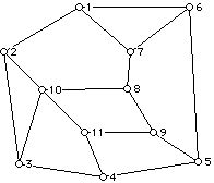
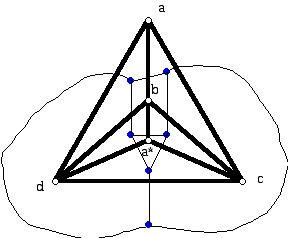
c. Given a graph J such as the one in Figure 1.
Can one find 11 segments in the plane labeled with the numbers 1 to 11 so that segment i intersects segment j if and only if edges i and j in I are joined by an edge (are adjacent)? If there are such segments, then J would be the "intersection" graph of the segments.
Question: Which graphs are the intersection graphs of segments in the Euclidean plane?
Do now 1:
Can you write down a geometrical question inspired by c. above?
Note: Geometry grows not so much because geometry questions that were first asked 50 years ago are being answered for the first time but because new questions that no one thought to ask in the past are being asked and answered.
Segments, lines, polygons, and polyhedra are commonplace objects in Euclid's Elements. In fact, some people regard the development of the Elements as leading up to the proof found in Book XIII of the Elements, where it is shown that there are 5 regular convex polyhedra. This is the modern way to state the result since Euclid does not discuss the concept of convexity. However, without the word "convex" the statement above is not true. Depending on the definition of polyhedron there can be more regular polyhedra. The history of the development of regular polyhedra is intriguing and shows how changes in the definitions of such fundamental objects as polygons and polyhedra have stimulated geometers to discover new facts.
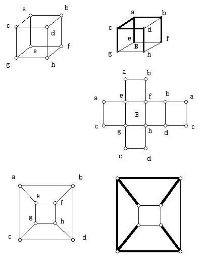
Here we use the theory of graphs as an organizing idea for a wide variety of new geometrical questions as well as providing insight into older geometrical results. Figure 2 shows a drawing of a 3-dimensional polyhedron on a flat piece of paper where some of the lines in the diagram are dotted to suggest that they are hidden and cannot be seen when one looks at this object in 3-dimensional space.
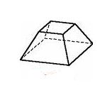
As a graph this polyhedron has 8 vertices, 12 edges, and 6 faces.
Do Now 2:
a. What are the names that are usually given to the faces of the polyhedron in Figure 2 when these faces are thought of as polygons? Are any of these faces congruent?
b. What is a "reasonable" name for this polyhedron?
Here (Figure 3) are some other drawings in the plane of graphs which are isomorphic to the graph in Figure 2.
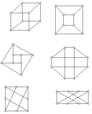
The most familiar of these drawings are the top two. As a graph, these graphs are all known as 3-cubes. We are not interested in lengths of lines here, nor whether straight lines are used in the representation (though above only straight lines are used), only the way the graph "hangs together." All of these graphs are isomorphic to each other. To express that two geometric objects are metrically equivalent, that is, that they have the same "distance" relationships among their parts, involves finding a geometric transformation which is known as an isometry between the objects.
Representing 3-dimensional objects in the plane
Although we live in a 3-dimensional world, we often have to represent objects on flat surfaces - planes. In addition to using hidden lines (Figure 2) there are other "tricks" that have been developed to do this. Among these tricks are the use of isometric and perspective drawings. Figure 4 shows two drawings of a cube which are typical of the ways that polyhedra are sometimes drawn on flat pieces of paper.
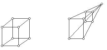
Another interesting approach to representing 3-dimensional polyhedra in the plane goes back to the German mathematician and artist, Albrecht Dürer. Dürer noticed that by cutting along the edges of a polyhedron sometimes one can unfold the polyhedron and flatten it out into the plane. The edges that one must cut form a spanning tree of the cube. A tree is a connected graph which has no circuits. A spanning tree of a graph H is a subgraph T which is a tree and which includes all the vertices of H. Figure 5 shows a cube sitting on the "base face" B, and in dark edges the edges of a spanning tree T which, when cut, will allow one to open up the cube and flatten it out so that it forms the polygon which has 14 vertices resembling a cross on its side. Figure 5 shows five fold lines drawn in the interior of the 14-gon. Such a diagram is sometimes referred to as a net. Strictly speaking, one needs in a situation of this kind to show which edges of the polygon must be pasted together to form the polyhedron because it turns out that the same polygon can sometimes be folded into two non-isometric polyhedra. In fact, sometimes one can get a convex and non-convex polyhedron each of which can be folded from the same net. Technically, nets should indicate fold lines because if one has a plane polygon but fold lines are not indicated, then it is conceivable, and can actually happen, that one can fold different polyhedra with different choices for fold lines. Also shown in Figure 5 is another drawing of the same cube (which does not have any edges that meet at points other than vertices) and the spanning tree corresponding to T (again shown with bold edges). It turns out there are surprisingly many different polygons which arise from the cube all of whose edges have the same length.
Do Now 3:
Verify that there are 11 different nets for the 3-cube.
Note: Metrical solids which have graphs which are combinatorially equivalent (such as the solid in Figure 2) can have many more than 11 different nets. It is still an open problem to determine the exact number of nets for various metrical solids which are combinatorial cubes.
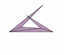
In light of the fact that all the nets of a 1x1x1 cube don't overlap, it may be a bit of a surprise that even for the tetrahedron there are metrical tetrahedra which for which there is at least one spanning tree which cannot be opened up without overlaps. The following example (Figure 6) is due to Makato Naniki. It turns out that this tetrahedron does have a spanning tree which will allow the polyhedron to be opened up flat.
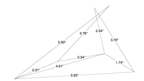
Here is a diagram (Figure 7) showing the lengths involved in actually constructing a version of the Naniki tetrahedron due to Branko Grünbaum.
It was G.C. Shephard, a British mathematician, who in 1975 appears to have been the first to call attention to this simple-to-state but unsolved problem:
Can one always cut along some set of edges of a convex 3-dimensional polyhedron and open the result to form a region in the plane with the property that the panels which form the faces do not overlap?
When large random polyhedra are generated, nearly all of the ways to open them up using a spanning tree do overlap. However, for any specific polyhedron which has been studied in an attempt to show that there is no spanning tree that works, the appropriate "needle in a haystack" spanning tree has been located which results in a net!
When a graph G can be drawn in the plane so that edges meet only at vertices, the graph is called planar, and a drawing without edges meeting except at the vertices is called a plane drawing of G or an embedding of G in the plane. A graph which has been drawn in the plane so that edges meet only at vertices is called a plane graph.
Figure 8 shows a planar graph H on the left but this drawing is not a plane drawing of the graph H. The graph on the right is isomorphic to the one on the left but has been drawn as a plane graph.
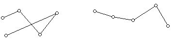
Figure 9 shows plane graph drawings of two polyhedra which exist in interesting metrical versions. These polyhedra are the triangular bipyramid P shown with dark edges and the triangular prism Q, which is shown with thin lines.
The diagram in Figure 9 is designed to show that these two graphs are "duals" of each other. This refers to the fact that the regions of P correspond to the vertices of Q and vertices of P correspond to the regions of Q .
Figure 10 shows a version of the triangular bipyramid designed to show that it can be constructed out of 6 equilateral triangles, thus making it one of the 8 convex polyhedra that can be made with equilateral triangles.
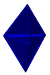
Do Now 4:
Draw all of the nets for the polyhedron in Figure 10. There are six equilateral triangle faces.
Figure 11 shows a sketch of a triangular prism. When all three of the four- sided faces are squares, then the two triangles must be equilateral triangles.
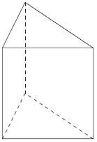
Do Now 5:
Determine all of the nets of a triangular prism which consists of three squares and two equilateral triangles.
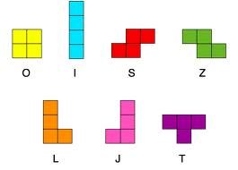
The nets of a cube can be thought of as six 1x1 squares which are attached along edges. We have already looked at the geometric structures called polygons. It is convenient to give squares which are attached along their edges and which lie in a plane a special name. The name used is polyomino and it was coined by the mathematician Solomon Golomb. For example, the polyominoes that can be made from four squares are known as the tetrominoes. Figure 12 shows the five possible tetrominoes.
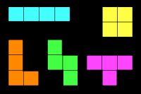
Two of the tetrominoes come in left and right handed versions. Figure 13 shows the tetrominoes where the right and left hand versions are shown.
However, in enumerating the tetrominoes it is usual to consider as different only those shapes that are not congruent. (It is impossible to transform the "left handed" L to the "right handed" J in the diagram above without using a reflection, which in essence lifts the L out of the plane, turns it over and sets it back down. The isometries of the plane, which don't involve going into the third dimension, are the translations and rotations. These transformations are sometimes called the rigid motions of the plane.
Do Now 6:
a. Draw all of the pentominoes, that is, shapes one can get by pasting together 1x1 squares along their edges. Which of the shapes you drew come in left and right handed versions?
b. Draw several hexominoes that cannot be folded up into a cube.
c. No formula is known to count the number of polyominoes with n square cells. As defined above it is possible for polyominoes to have holes. Can you draw a polyomino with as few squares as possible that has a hole? Some people modify the definition of polyomino to rule out having holes.
d. Can a polyomino have an odd length perimeter? What are the maximum and minimum perimeter of a pentomino?
e. What is the area of a polyomino with n squares?